 Your connection to advanced PCB manufacturing
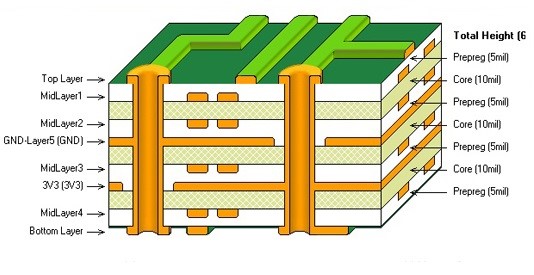
All About Stackups
Here are some of the standard stackups we use at Royal Circuits.
Stackup Details
For many designs the stackup and material type are critical, and at Royal Circuits we can help you in the design process. Changing the stackup is easy to modify down to .003 layer to layer spacing. The design should dictate the stackup and not the other way around.
Here are the standard stackups that we use at Royal Circuits for a .062 board needing 1 oz of copper.
Click below to view the stackup details.
These might be our standard builds, but it is routine to change it and usually there is no additional charge for changing material thickness.
For jobs that have impedance requirements we have the full suite of software that shows all the material used in your PCB along with the calculated impedances. It will also create a TDR coupon specific for your design that we can test to verify that the finished product matches the calculations.
There are lots of designs that the layer to layer spacing is important – including high speed designs, internal capacitance may be a factor, and different RF. You can work with us so it can be fully specified on the print prior to placing the order and that way future revisions will be built the same way.
Standard Stackup Requirements
Customer Information
- Contact Name
- Part Number (optional)
- Revision (optional)
- Tool # (Can be same as part#, it is how your design will be identified.)
Standard Stackup Information / Controlled Impedance
- Layer Identification ( Signal, Plane, Mixed) This is based on copper area not function.
- Ohms required + tolerance. (Example: 50 ohms +/-10%)
- Layers with required impedance.
- Drills including top to bottom thru drill.
- Type of Impedance Design (SE-single ended, Diff-differential pairs)
- SEco-single ended coplanar, Diffco-differential coplanar).
Optional Unless Different from STANDARD (See Below)
- Copper thickness – STANDARD = 1 oz. finished
- Board finished thickness – STANDARD = .062”
- Material type(s) – STANDARD = 370HR
- Line widths for requested impedance – STANDARD = 5-10 mils (.005-.010”)
- Trace width spacing, for differential and coplanar – STANDARD 5-10 mils (.005-.010”)

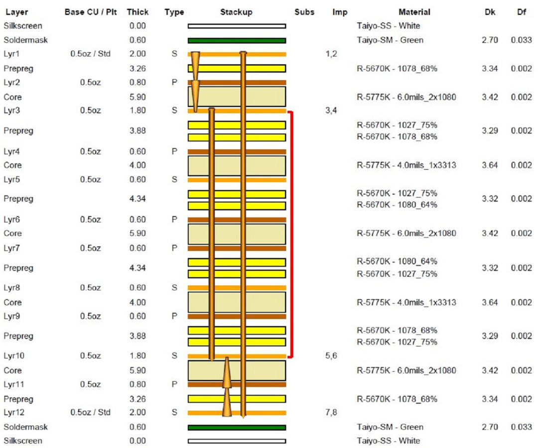
12-Layer Blind Stack-Up Example
| Type | Req. Thick | Tol% + | Tol% - | Act. Thick | Measured |
|---|---|---|---|---|---|
| Overall | 62.0 | 10.0 | 10.0 | 62.7 | |
| Over Lamination | 58.4 | 10.0 | 10.0 | 58.7 | |
| Over Laminate | 57.2 | 10.0 | 10.0 | 57.5 | |
| Over Metal | 60.8 | 10.0 | 10.0 | 61.5 | |
| Sub-assembly 3-10 | 35.1 |
| Type | Layer | Design Line | Actual Line | Spacing (traces) | Spacing (ground) | Ref Lyrs | Target (ohms) | Tolerance (ohms) | Predicted (ohms) |
|---|---|---|---|---|---|---|---|---|---|
| Single Ended | Lyr1 | 6.0 | 6.0 | 0/2 | 50.0 | 5.0 | 49.9 | ||
| Differential | Lyr1 | 5.0 | 5.0 | 9.0 | 0/2 | 100.0 | 10.0 | 100.4 | |
| Single Ended | Lyr3 | 4.0 | 4.2 | 2/4 | 50.0 | 5.0 | 50.4 | ||
| Differential | Lyr3 | 4.0 | 4.0 | 10.0 | 2/4 | 100.0 | 10.0 | 100.2 | |
| Single Ended | Lyr10 | 4.2 | 4.2 | 9/11 | 50.0 | 5.0 | 50.4 | ||
| Differential | Lyr10 | 4.0 | 4.0 | 10.0 | 9/11 | 100.0 | 10.0 | 100.2 | |
| Single Ended | Lyr12 | 6.0 | 6.0 | 11/0 | 50.0 | 5.0 | 49.9 | ||
| Differential | Lyr12 | 5.0 | 5.0 | 9.0 | 11/0 | 100.0 | 10.0 | 100.4 |
| Material | Quantity / Panel | Total Quantity |
|---|---|---|
| 6.0 mils H/H core | 3 | 3 |
| 4.0 mils H/H core | 2 | 2 |
| 0.5 oz. foil | 2 | 2 |
| 1078 prepreg | 4 | 4 |
| 1027 prepreg | 4 | 4 |
| 1080 prepreg | 2 | 2 |
| White silkscreen | 2 | 2 |
| 19 | 19 |
Additional Stack-Up Information

All About PCB Stackups
Determining the right PCB stackup configuration is one of the most important aspects to achieving ...
PCB Stackups & Impedance Control
Learn about material stackups and impedance control with Royal Circuits dedicated stackup engineer Teresa Jensen. ...

What Do You Need for an Impedance Controlled Stackup? Omar Tells Us That and More!
Omar Madrigal, the Director of Planning Engineering at Royal Circuits tells us about travelers, stackups ...