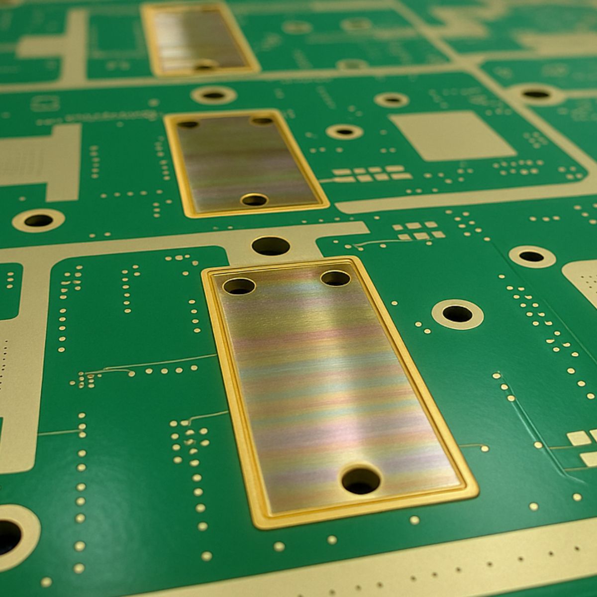
Managing localized thermal loads is increasingly critical as power densities rise. One solution to this problem is using heat sinks within embedded cavities—a strategy aligning with IPC-2221B guidelines for thermal management and board structure. This approach supports high-reliability applications in aerospace, defense, and power electronics by improving thermal transfer efficiency without increasing the board’s external footprint.
The Thermal Role of Embedded Heat Sinks
Heat sinks embedded into PCB cavities help extract thermal energy from high-power components and dissipate it across a broader conductive area. This method bypasses the limitations of surface-mounted cooling strategies and aligns with IPC-9592B recommendations for thermal performance in power conversion devices.
Key advantages include:
- Z-axis space efficiency: Reduces overall PCB height, supporting form factor constraints in military, medical, and portable systems.
- Direct thermal pathways: Improves heat transfer coefficients by placing thermal vias or solder directly between the heat source and the heat sink structure.
- Improved structural and environmental durability: Protects components from shock, vibration, and external contaminants.
IPC-Driven Considerations for Embedded Heat Sink Integration
Material Selection
IPC standards emphasize both thermal performance and manufacturability. Based on IPC-4101 and IPC-2221:
- Aluminum (Al): Lightweight and thermally conductive (~200 W/m·K), compliant with most FR-4 stackups.
- Copper (Cu): High-performance (>390 W/m·K), though heavier and more challenging to etch or laminate.
- Advanced composites: Including graphene-infused films or ceramic matrix composites are emerging under IPC exploratory material classes.
Cavity Design and Stack-Up Optimization
According to IPC-6012 and IPC-6018:
- Cavity depth should support direct thermal interface material (TIM) contact or solder attach without compromising dielectric integrity.
- Tolerance analysis must account for Z-axis deformation during lamination.
- DFM/DFX practices suggest maintaining minimum copper clearances per IPC-2221 for isolation from active layers.
Fabrication and Assembly Challenges
Controlled-Depth Milling and Isolation
Creating cavities for embedded sinks typically involves:
- Controlled-depth routing per IPC-6012 Class 3 standards for high-reliability applications.
- Electrical isolation techniques, such as dielectric coatings (e.g., polyimide, ceramic-filled epoxies), are mandatory where conductive sinks are near voltage planes.
Assembly Methods
IPC-7095 and IPC-A-610 recommend:
- Thermally conductive pastes or soldering for direct bonding.
- Vacuum lamination techniques to minimize voiding in TIM layers.
- Quality assurance must include X-ray and scanning acoustic microscopy (SAM) inspection for delamination or void detection.
Examples of Applications in Mission-Critical Systems
- Defense and Aerospace: Embedded thermal sinks reduce weight while improving MIL-PRF-31032 compliance for ruggedized electronics.
- High-Performance Computing (HPC): Enables thermal uniformity across densely packed CPUs and GPUs in IPC Class 3/A boards.
- Power Electronics: Supports IPC-9592B guidelines for power module thermal margins and stress testing.
- Medical Devices: Enhances miniaturization of defibrillators, imaging hardware, and surgical robotics.
Future Trends and IPC Roadmap Alignment
Innovations such as microfluidic cooling channels, phase-change thermal interfaces, and vapor chambers are being integrated at the PCB substrate level—particularly in next-gen 2.5D and 3D integration environments. These approaches align with recommendations from the IPC Heterogeneous Integration Roadmap (HIR) and the Advanced Packaging Initiative.
IPC-CFX (Connected Factory Exchange) protocols are also being used to automate temperature and thermal stress monitoring, creating traceable, standards-compliant digital records of heat sink performance during in-circuit tests (ICTs) and burn-in stages.
Conclusion
By embedding heat sinks within cavities using IPC-compliant design and fabrication techniques, engineers can meet stringent thermal, mechanical, and reliability demands. This not only improves system longevity and performance but supports scalable design frameworks in line with predictive engineering principles and smart factory goals.
 Your connection to advanced PCB manufacturing


