 Your connection to advanced PCB manufacturing
A Quantitative Path for Resistance
The Galvanometer
In 1820, Hans Christian Oersted and Andre-Marie Ampere discovered that a current passing through a wire would torque compass needle in a direction that is at a right angle to the direction of the current, and that discovery led to the creation of the uncalibrated tangent galvanometer.[1][2] These devices use a current to displace a magnetized needle in the presence of Earth’s magnetic field. Unfortunately, each of these instruments had an unknown calibration constant due to the variability and orientation of the Earth’s magnetic field near the test location.
A Constant Potential Difference Source
Two years later, Thomas Seebeck discovered that two dissimilar metals with junctions held at two different temperatures would cause a deflection in a compass needle held near a wire. Seebeck attributed it to magnetism, but other scientists at the time believed it generated a voltage.[3] This thermoelectric-effect reliably produced a repeatable constant potential difference source that voltaic piles of the time could not.
In 1825, a half-century after Cavendish performed his unknown and rudimentary experiments, and with two new tools in hand, Georg Ohm used the thermocouple and a galvanometer to quantitatively determine the relationship between the torque on the galvanometer and the length of a connecting wire. The following equation is the result of Ohm’s experiment.
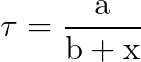
The torque, τ, on the galvanometer was directly proportional to a constant (a) determined by the temperature difference and inversely proportional to the total of the resistance of the circuit (b) and the wire (x)[4]
This is not the equation normally attributed to Ohm. Ohm did not invent the Ohm’s Law we know today – he found a quantitative relationship between the temperature differential of a thermocouple, the length of wire, some constant in his system, and the torque on a galvanometer.
In his text on “Teaching Introductory Physics”, Arnold Arons notes that Ohm kept the diameter of the wire as a constant and experimented with different metals, noting that “the equation fits experiment very accurately nearly up to the extinction of the force by the resistance of the conductors.” In other words, there is no minimum potential difference needed to overcome resistance in a conductor. This is a very important finding[5].
Ohm’s Law was likely developed without any knowledge of Cavendish’s work. But it didn’t become Ohm’s Law for several more years. In the next article we’ll take a look at James Prescott Joule’s discovery of Joule Heating.
Most current Physics textbooks appear to begin the study of electricity by teaching electrostatics and then transitioning into steady-state dc current with Ohm’s law as the first important lesson. Ohm’s Law is often presented in textbooks as the necessary bridge between electrostatics and electric current. That may or may not be an appropriate entry point for Ohm’s law as we now know it. But it certainly doesn’t quite explain the introduction of the power law. Other than the fact they use similar variables, there isn’t a compelling reason to introduce the power law at this time, except, perhaps, it allows teachers and authors to discuss the brightness of lightbulbs (power dissipation) in series and parallel circuits. As Arnold Arons points out on page 203 of his textbook “Teaching Introductory Physics”, “because of the way in which most textbooks introduce resistive circuits and concentrate problems and exercised on manipulation of Ohm’s law and [the power law], very few students absorb awareness of the fact that current in a system is not always determined by [I=ΔV/R]”.
A Qualitative Path for Resistance
James Clerk Maxwell published the “Treatise on Electricity and Magnetism” in 1873. The following year, Maxwell acquired the previously unpublished work of Henry Cavendish’s experiments from 1772-1773. In 1879, Maxwell published the work in a book titled “The Electrical Researches of Henry Cavendish.”[1]
In “The Electrical Researches of Henry Cavendish” chapter titled “Resistance to Electricity”[2], Cavendish attempted to quantify the resistance of various materials and mixtures, including measured lengths of conductors. Cavendish did this by simultaneously charging 6 identical Leyden jars with connecting wires and then he removed the wires to leave each jar with an identical amount of charge.
Then, Cavendish sequentially discharged the jars through a test circuit that consisted of a carefully measured length of wire, a bit of tinfoil, and a spark gap.[3] The limitations of the apparatus available to Cavendish at the time prevented a truly quantitative experiment. Still, he noticed the strength of shock he received and the brightness of a spark related to wire length.
Cavendish’s 1772-1773 work wasn’t well known in the scientific community because he apparently never published it. His apparatus lacked the precision required to develop an accepted mathematical relationship between resistance and the physical properties of a wire, but it was similar in spirit to an experiment later performed by Georg Ohm.
Physics labs have electrostatic generators that are capable of reproducing the experiment. However, they seldom perform an experiment that demonstrates a relationship between a length of wire and the strength of a shock.
Had Cavendish published his results, it might have led credibility to Ohm’s work and led to quicker acceptance in the broader scientific community.
Footnotes: