Historically PCB fabrication and delivery of finished products preceded test methods to validate the PCBs. In the 1970’s PCBs were fabricated and shipped without electrical test validation. Mania brought electrical testing to the industry and soon after electrical testing became standard and a requirement for all but the simplest products.
For the next decade PCBs were built by using a “Golden” board programming. The Golden board method used a finished PCB from a finished lot of PCBs and placed on a test fixture, an operator would place the PCB on a tester and initiate a self-learned shorts and opens program from the board. If the second PCB matched the first, a Golden board was established. One of the short comings of the Golden board testing however, is that it is susceptible to missing errors in the supplied fabrication data. The Golden board method would also allow for CAM errors to go undetected up to assembly. The solution finally came when CAM and net compare was made available in the late 1980s. Software was used to validate the received data before fabrication started, the same software was then used to generate an ET program to validate the finished PCB. This method saved product cycle time, prevented the loss of material, and saved manufacturing time at both PCB fabrication and assembly.
The same experience could be said about TDR, and AOI program downloading.
Today the industry is facing the challenge regarding microvia reliability, especially after the reflow of the PCB at assembly, during rework or operating in the field. As with electrical testing in the past, the industry designed PCBs using microvias without evaluating the thermal properties of the material or the geometries in the design. Fabricators produced the finished goods and evaluated the finished PCB to established standards such as IPC-6012. When difficult-to-detect failures occurred post-assembly a test method IPC-TM-650 2.6.27 was established and a caution was added to IPC-6012 rev in section 3.6 Structural Integrity. The testing of a D coupon via IPC-TM-650 2.6.27 did validate that the finished PCBs were safe for assembly, but it did not stop a fabricator from building a bad design. However, until now, there wasn’t a method to simulate a PCB design that validated that the material selection, dielectric thickness, microvia size, and configuration (single, stacked, or staggered microvias) could survive 6x reflows.
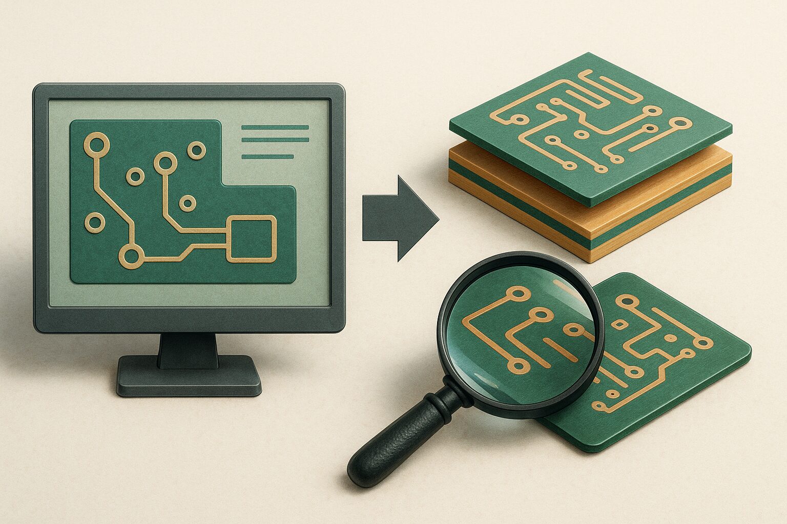
As with the evolution of electrical test and the use of the software to validate the design and the final test, we now have software that will validate the structural integrity of a microvia in a design before a PCB stack-up has been approved and implemented into the fabrication process. Our industry now has the opportunity to validate the design, fabricate a microvia design with confidence, and validate that the PCB has met the structural requirements by OM testing to IPC-TM-650 2.6.27.
For more information, listen to Gerry Partida on Altium’s podcast, Design Reliable Multiple Stack Microvias Like a Pro (altium.com).
 Your connection to advanced PCB manufacturing


